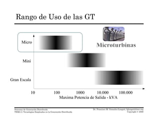
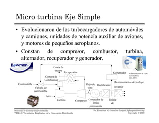
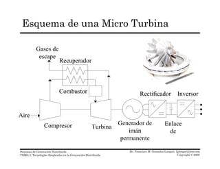
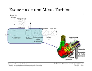
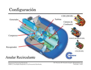
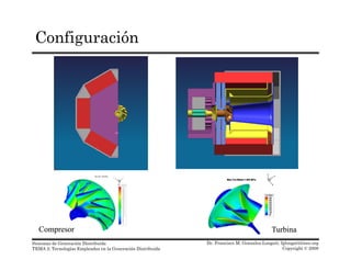
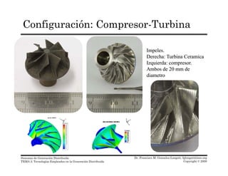
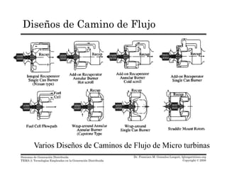
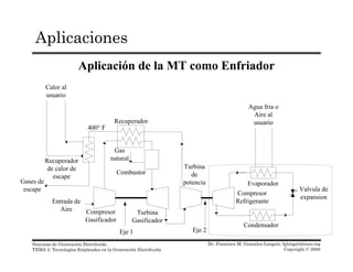
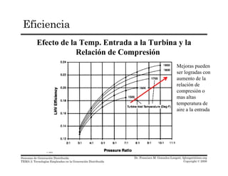
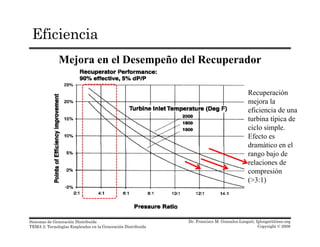
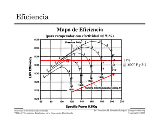
Este documento describe las microturbinas, una tecnología empleada en la generación distribuida. Explica que las microturbinas son pequeños motores de ciclo Brayton que usan combustión para producir electricidad. Describe las características, clasificaciones, componentes y diseños de las microturbinas, incluyendo su compresor, turbina, generador y uso de gas natural como combustible.
El técnico debe conocer todo sobre metales de biela, rectificaciones del mono bloc y lubrican sobre la bomba de aceite cuando se debe cambiar, de acuerdo a estos datos y hacer las correcciones del caso el motor debe operar de acuerdo a los datos del fabricante.
MOTOR STIRLING, OCUPA 4 PRINCIPIOS DE LA TERMODINAMICA:
1. Expansión isotérmica
2. Proceso Isovolumétrico (Perdida de calor)
3. Compresión Isotérmica
4. Proceso Isovolumétrico (Ganancia de calor)
Tiristor Desactivado Por Compuerta - GTOJorge Marin
Tiristor desactivado por compuerta (GTO)
Son semiconductores discretos que actúan como interruptores completamente controlables, conocidos simplemente como GTO (Gate Turn-Off Thyristor), los cuales pueden ser encendidos y apagados en cualquier momento con una señal de compuerta positiva o negativa respectivamente. Estos componentes están optimizados para tener muy bajas pérdidas de conducción y diseñados para trabajar en las mas demandantes aplicaciones industriales. Estos componentes son altamente utilizados en Convertidores de Alto Voltaje y Alta Potencia para aplicaciones de baja y media frecuencia.
Un tiristor GTO, al igual que un SCR puede activarse mediante la aplicación de una señal positiva de compuerta. Sin embargo, se puede desactivar mediante una señal negativa de compuerta. Un GTO es un dispositivo de enganche y se construir con especificaciones de corriente y voltajes similares a las de un SCR. Un GTO se activa aplicando a su compuerta un pulso positivo corto y se desactiva mediante un pulso negativo corto. La simbología para identificarlo en un circuito es la que se muestra en la figura .
Descripción técnica de los componentes del motor diésel tener mayor conocimiento de los componentes del motor, sistemas finalidad, partes y para su armado del motor diésel.
Enlace a video https://youtu.be/vhdQtNVu4nQ
En esta lista de videos se describen los fundamentos de la oleohidráulica, los componentes más importantes, circuitos hidráulicos simulados en Fluid Sim H
Visita el Canal de Youtube https://youtube.com/playlist?list=PLHTERkK4EZJrRX0CoeyKJ3x9879aBwOga
Visita el Blog https://www.mecatrónica.com.co/p/hidraulica.html
Si te ha sido útil, regálame un Like, comenta y suscríbete :) (◕‿◕)
Visita el Canal de Youtube http://www.youtube.com/c/JovannyDuque?sub_confirmation=1_
Visita el Blog https://www.xn--mecatrnica-lbb.com.co/
Visita el Blog https://mecatronica-itsa.blogspot.com/
Visita el Blog https://www.mecatrónica.com.co/
Future Energy Systems: Challenges on Modelling and Control Uncertainties + Bi...Francisco Gonzalez-Longatt
Future Energy Systems: Challenges on Modelling and Control Uncertainties + Big-Data. 3th April 2015
Kasetsart University Bangkok, Thailand. Prof. Francisco M. Gonzalez-Longatt
WORKSHOP: Frequency Control Schemes and Frequency Response of Power Systems c...Francisco Gonzalez-Longatt
The frequency of a power system depends on real power balance: generation-demand. During the normal operation of a power system, the frequency is regulated within strict limits by adjusting the electrical supply to meet the demand. If the balance between generation and demand is not reached, the system frequency will change at a rate initially determinate by the total system inertia. The total system inertia comprises the combined inertia of most of spinning generation and load connected to the power system. The contribution of the system inertia of one load or generator depend if the system frequency causes change in its rotational speed and, then, its kinetic energy. Worldwide, electricity generation from renewable energy is increasing rapidly; it is especially true in terms of the increasing of the wind power penetration. This situation arise some issues regarding the system frequency control because wind turbines provide small or even none response to frequency changes. Power electronically controlled and/or power electronically connected generators such as DFIG and FPC wind turbines do not naturally provide inertia response. However inertia response can be emulated by adding a supplementary control signal proportional to the rate of change of frequency, this is named the Synthetic or Artificial Inertia. This approach imposes some challenges about control and protection systems. This workshop is designed to provide a general understanding of the frequency control schemes and frequency response of power systems with the integration of wind power penetration.
Seminar: Modelling Renewables Resources
and Storage in PowerFactory V15.2
This is a very simple seminar designed to present a general overview of the modelling renewables (Wind and PV) and storage (Batteries) in PowerFactory. This is not a 2 day training, it is a simple 90 minutes presentations. I hope you enjoy it.
Modelación y Simulación de Sistemas de Potencia Empleando DIgSILENT PowerFact...Francisco Gonzalez-Longatt
Los participantes en este entrenamiento disfrutarán de una experiencia de aprendizaje única, en la cual se presenta una introducción exhaustiva e integral de las funciones básicas de software DIgSILENT PowerFactory.
El participante de este entrenamiento obtendrá una visión completa de las principales funcionalidades del programa de DIgSILENT PowerFactory.
1st Symposium on Modelling and Simulation Challenges for Future Sustainable Energy Systems.
Tutorial: Modelling and Simulations: Renewable Resources and Storage
Content:
Basic PowerFactory Concepts
Overview of System Analysis Functions
Dynamic Modelling with PowerFactory
Types of Wind Turbines Technologies
WTG Models for Load Flow and Short Circuit Calculation
Global “Templates” library
WTG Models for Dynamic Simulation
Fully Rated WTG Template
PV and Battery Energy Storing System (BESS)
The Book…
Design and Analysis of PID and Fuzzy-PID Controller for Voltage Control of DC...Francisco Gonzalez-Longatt
DC microgrids are desired to provide the electricity for the remote areas which are far from the main grid. The microgrid creates the open horizontal environment to interconnect the distributed generation especially photovoltaic (PV). The stochastic nature of the PV output power introduces the large fluctuations of the power and voltage in the microgrid and forced to introduce the controller for voltage stability. There are many control strategies to control the voltage of a DC microgrid in the literature. In this paper the proportional-integral-derivative (PID) and fuzzy logic PID (FL-PID) controller has been designed and compared in term of performance. Performance measures like maximum overshoot and settling time of FL-PID compared with the PID proved that the former is better controller. The controllers are designed and simulated in the MATLAB programming environment. The controllers has been tested for the real time data obtained from Pecan Street Project, University of Texas at Austin USA.
El alto rendimiento y la duración sin igual de la Excavadora Hidráulica 345D L se combinan para
proporcionar máxima productividad, El sistema hidráulico ha sido diseñado para
proporcionar fiabilidad y excelente control
de la operación. Un sistema optativo de control
de las herramientas proporciona una mayor
flexibilidad a la máquina, Estación del operador
Proporciona espacio amplio, excelente
visibilidad y fácil acceso a todos los
interruptores. El monitor tiene una pantalla
gráfica en color que permite al operador
entender fácilmente la información de
la máquina. En su conjunto, la cabina
proporciona un ambiente cómodo para
el operador,A través de Cat® Work Tools (Herramientas
Cat) se encuentra disponible una gran variedad
de herramientas que incluyen cucharones,
acopladores, martillos y cizallas, Caterpillar ofrece una amplia variedad de
accesorios optativos e instalados en fábrica
para mejorar el rendimiento y la administración
del equipo en el sitio de trabajo.
Brochure, Folleto, Specalog, oroscocatt, oroscocat
catalogo 345DL CAT pdf
Similar a Capitulo 2.3: Microturbina - Sistemas de Generacion Distribuida (20)
The total system inertia (H) is the primary source of electricity system robustness to frequency disturbances which arise due to an imbalance of generation and demand. The traditional large synchronous generators directly connected to the grid are the main sources of inertia, and they play an important role in limiting rate of change of frequency (ROCOF) and provide a natural response to the system frequency changes following an unscheduled loss of generation or demand from the power system.
The transition to a low carbon society is the driving force pushing the traditional power system to increase the volume of non-synchronous technologies which mainly use power converters (PCs) as an interface to the power network. The PCs decoupled the primary source from the power network, as a consequence are not able to contribute with “natural” inertia in the same way as classical synchronous generators. During a system frequency disturbance (SFD), the system frequency will change at a rate initially determined by the total system inertia (H). The inertial response of the system might be negatively affected with devastating consequences for system security and reliability.
The objective of this seminar is to present the fundamental aspects about system Frequency Control in Low Inertia Systems.
This seminar has special emphasis on non-synchronous technologies, mainly using power converters (PCs): (a) High Voltage DC (HVDC) and (b) Wind Power Integration and considers the implications on frequency control.
The total system inertia (H) is the primary source of electricity system robustness to frequency disturbances which arise due to an imbalance of generation and demand. The traditional large synchronous generators directly connected to the grid are the main sources of inertia, and they play an important role in limiting rate of change of frequency (ROCOF) and provide a natural response to the system frequency changes following an unscheduled loss of generation or demand from the power system.
The transition to a low carbon society is the driving force pushing the traditional power system to increase the volume of non-synchronous technologies which mainly use power converters (PCs) as an interface to the power network. The PCs decoupled the primary source from the power network, as a consequence are not able to contribute with “natural” inertia in the same way as classical synchronous generators. During a system frequency disturbance (SFD), the system frequency will change at a rate initially determined by the total system inertia (H). The inertial response of the system might be negatively affected with devastating consequences for system security and reliability.
The objective of this seminar is to present the fundamental aspects about system Frequency Control in Low Inertia Systems.
This seminar has special emphasis on non-synchronous technologies, mainly using power converters (PCs): (a) High Voltage DC (HVDC) and (b) Wind Power Integration and considers the implications on frequency control
The total system inertia (H) is the primary source of electricity system robustness to frequency disturbances which arise due to an imbalance of generation and demand. The traditional large synchronous generators directly connected to the grid are the main sources of inertia, and they play an important role in limiting rate of change of frequency (ROCOF) and provide a natural response to the system frequency changes following an unscheduled loss of generation or demand from the power system.
The transition to a low carbon society is the driving force pushing the traditional power system to increase the volume of non-synchronous technologies which mainly use power converters (PCs) as an interface to the power network. The PCs decoupled the primary source from the power network, as a consequence are not able to contribute with “natural” inertia in the same way as classical synchronous generators. During a system frequency disturbance (SFD), the system frequency will change at a rate initially determined by the total system inertia (H). The inertial response of the system might be negatively affected with devastating consequences for system security and reliability.
The objective of this seminar is to present the fundamental aspects about system Frequency Control in Low Inertia Systems.
This seminar has special emphasis on non-synchronous technologies, mainly using power converters (PCs): (a) High Voltage DC (HVDC) and (b) Wind Power Integration and considers the implications on frequency control.
During the normal operation of a power system, the frequency is regulated within strict limits by adjusting the electrical supply to meet the demand. If the balance between generation and demand is not reached, the system frequency will change at a rate initially determinate by the total system inertia. The total system inertia comprises the combined inertia of most of spinning generation and load connected to the power system. The contribution of the system inertia of one load or generator depend if the system frequency causes change in its rotational speed and, then, its kinetic energy. Worldwide, electricity generation from renewable energy is increasing rapidly; it is especially true in terms of the increasing of the wind power penetration. This situation arises some issues regarding the system frequency control because wind turbines provide small or even none response to frequency changes. Power electronically controlled and/or power electronically connected generators such as DFIG and FPC wind turbines do not naturally provide inertia response. However, inertia response can be emulated by adding a supplementary control signal proportional to the rate of change of frequency, this is named the Synthetic or Artificial Inertia. This approach imposes some challenges about control and protection systems. This workshop is designed to provide a general understanding of the frequency control schemes and frequency response of power systems with the integration of wind power penetration.
Effects of Grounding Configurations on Post-Contingency Performance of MTDC...Francisco Gonzalez-Longatt
-The grounding system is extremely important, as it affects the performance of the MTDC system virtually in any possible mode: normal (asymmetrical operation) and abnormal operation (faults), steady-state and dynamic. The objective of this paper is to introduce a simple approach to assess the steady-state post-contingency of multi-Terminal HVDC System and uses it order to illustrate the effects of grounding configurations on steady-state post-contingency performance. A 3-terminal HVDC system is used to formulate the main theoretical framework for performance prediction on post-contingency steady-state of MTDC system as well as for demonstrative purposes.
Una señal analógica es una señal generada por algún tipo de fenómeno electromagnético; que es representable por una función matemática continua en la que es variable su amplitud y periodo en función del tiempo.
Se denomina motor de corriente alterna a aquellos motores eléctricos que funcionan con alimentación eléctrica en corriente alterna. Un motor es una máquina motriz, esto es, un aparato que convierte una forma determinada de energía en energía mecánica de rotación o par.