Descargado 465 veces
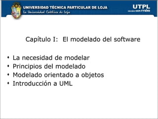


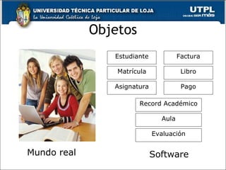
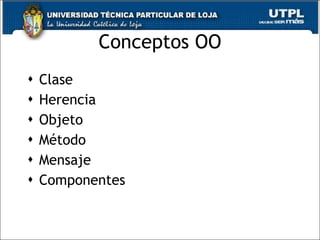
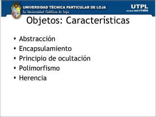
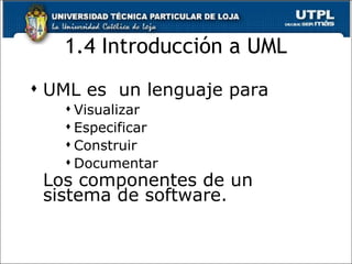


El documento introduce los conceptos básicos de modelado de software, incluyendo la necesidad de modelar, los principios del modelado y el modelado orientado a objetos. Explica que los modelos son simplificaciones que nos ayudan a comprender sistemas complejos, y que la elección de los modelos influye en la solución. También presenta el lenguaje UML, que permite visualizar, especificar, construir y documentar los componentes de un sistema de software.