
Recomendados
Recomendados
Más contenido relacionado
La actualidad más candente
La actualidad más candente (20)
Similar a SEMANA.pptx
Similar a SEMANA.pptx (20)
Más de Sunielrusber
Más de Sunielrusber (15)
Último
Último (20)
SEMANA.pptx
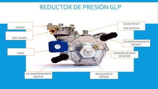
- 1. REDUCTOR DE PRESIÓN GLP CONEXIÓN DEVACÍO DE MOTOR SALIDA DE GLP FASE GASEOSA ELECTROVÁLVULA DE CORTE ENTRADA DE GLP FASE LÍQUIDA REGULADOR DE PRESIÓN SALIDA/ENTRADAREFRI GERANTE FILTRO DE FASE LÍQUIDA SALIDA/ENTRADAREFRI GERANTE
- 2. • Normativa Internacional R110/ISO • Normativa COVENIN 3226-1-97 Cilindros • Normativa COVENIN 3227-09 Componentes de sistema • Normativa COVENIN 3228-99 Instalación y pruebas del sistema • Normativa COVENIN 3683-1 Talleres de conversión
- 3. Arquitectura de la gestión electrónica de un sistema de inyección
- 4. • Explota la información que proviene de los diferentes sensores y, a partir de programas y cartografías de su memoria, comanda los elementos siguientes: Relés de activación (Alimentación bomba de gasolina, etc.) Inyectores. Bobinas de encendido. Electroválvula de purga del cánister. Actuador ralentí. • Atención: dependiendo de los montajes, se debe respetar un procedimiento de reinicialización después de desconectar la batería. Sistema de inyección a gasolina Electronic Control Unit (ECU)
- 6. ECU (Electronic Control Unit) Microprocesador automotriz 16 bit 50 Mhz Controla hasta un máximo de 4 inyectores Efectúa el auto diagnostico de sensores y actuadores Temperatura de trabajo – 40° a 100°C Comunica el PC con la ECU mediante interface
- 7. Señales de input/output ECU LandiRenzo LC02/OMEGAS INPUT • Tiempo de inyección de Gasolina • Señal de rpm • Señal de temperatura del agua • Señal de presión de GNV o GLP • Señal de temperatura de GNV o GLP • Señal de nivel de GNV o GLP • Señal lanbda OUTPUT • Tiempo de inyección de GNV o GLP • Apertura/clausura electroválvula • Indicación de nivel de combustible • Puerto diagnóstico PC
- 9. RIEL DE INYECTORES Es el encargado de dosificar la cantidad exacta de Gas, en su fase gaseosa, con su temperatura de suministro y direccionada a cada cilindro. Entrada de gas Tapón Base de goma Boquillas de riel (STD 1.5 MM) Bobina de riel (2Ω) Rampa Regulador de carrera del émbolo
- 10. Riel de inyectores Corriente de pilotaje: 4 / 1A “Peak and hold” Alimentación: 6 16 volt Temperatura de trabajo: -40°C +120°C Presión de trabajo: 0.8 3 bar Tiempo de apertura@12V: 1.5 ms Dimensión: Ø 32 x h 73 mm Peso: 120 g Homologación: ECE R 110 @ -40°C MIN. ECE R 67/01
- 11. CORRECTO MONTAJE Los Inyectores de GAS (GLP-GNV) deben estar contados con una base de metal y sostenidos en una base de goma, para amortiguar la resonancia mecánica.
- 12. MONTAJE DE LAS MANGUERAS DE GAS Los Inyectores de GAS (GLP-GNV) están montados en conjuntamente con las boquillas de Inyección, por medio de mangueras de baja presión, las mismas que deben tener la misma longitud y diámetro de sección.
- 13. MANTENIMIENTO DEL RIEL DE INYECCIÓN El riel de inyección esta compuesto : •4 inyectores de gas •Sensor de presión y temperatura de gas Estos componentes no requieren mantenimiento periódico. •En caso de que el sensor no genere señal se debe reemplazar. •El filtro de los inyectores tiene garantía de por vida, sin embargo se puede limpiar de ser necesario. Filtro del inyector de gas.
- 14. ¿Cómo realizo un Corte de inyectores? Equipos Visual A través de los colores de los cables de los inyectores RECONOCIMIENTO DEL PULSO DE INYECCIÓN
- 15. Ecu de Gasolina Ecu de Gas A A A A FUNCIONAMIENTO EN GASOLINA Importante : El pulso de Inyección (negativo) llega a excitar a la bobina del inyector de Gasolina, logrando la inyección de Gasolina.
- 16. Ecu de Gasolina Ecu de Gas B A B A FUNCIONAMIENTO EN GAS Importante : El pulso de Inyección (negativo) NO llega a excitar a la bobina del inyector de Gasolina, como consecuencia no se genera la inyección de Gasolina.
- 17. Comparación Funcionamiento en Gas Funcionamiento en Gasolina
- 18. Conmutador El conmutador indica el nivel del gas y selecciona el combustible (gas/bencina).Viene dotado de un “buzzer” para avisar el cambio automático a bencina cuando la ECU entra en diagnóstico, o se termina el gas.
- 20. Emulación de los Inyectores de Gasolina, para un motor de 4 Cilindros.
- 23. 616484000-0 Rev.080211-0 2-12 Il presente documento non può essere riprodotto né portato a conoscenza di terzi senza autorizzazione della ditta A.E.B. S.p.A. This document may not be reproduced or made known to any third party without permission of the company AEB S.p.A. MP48 4 CYL. INJECTION CONTROL UNIT INSTALLATION MANUAL AEBAlternative Fuel Electronics via dell’industria 20 42025 - Cavriago- Italy ph. +39 0522 494401 - fax.+39 0522 494410 www.aeb.it -info@aeb-tech.com technical assistance ph. +39 0522 494414 - fax.+39 0522 494410 aebasst@aeb-tech.com a divisionof AVVERTENZE GENERALI/GENERALINFORMATION Dove fissare la Centralina / Where to install the control unit: - LONTANO da possibili INFILTRAZIONI D’ACQUA. - FAR from any WATER LEAKAGE - LONTANO da ECCESSIVE FONTI DI CALORE (esempio collettori di scarico). - FAR from EXCESSIVE HEAT SOURCES (such as exhaust manifolds). - LONTANO dai CAVI DELL’ALTA TENSIONE. - FAR from HIGH-VOLTAGE CABLES. Fare delle buone connessioni elettriche evitando l’uso dei “RUBACORRENTE”. Si tenga presente che la migliore connessione elettrica è la saldatura debitamente isolata. Create efficient electrical connections without using any “POWER TAPS”. Properly insulated soldering is the most effective type of electrical connection. Avvisare il cliente che in caso di rottura del fusibile dell’impianto a GAS, il Sistema ripri- stina i collegamenti dei dispostivi a cui è collegato. Si sconsiglia vivamente di sostituire il fusibile con un’altro di amperaggio maggiore, cio’ puo’ provo- care danni irreparabili. Advise the customer that if the GAS system fuse burns, the connections of the devices to which it is connected will be restored. It is strongly recommended not to replace the fuse with another one with a higher amperage rating since it may cause irreparable damage. Non aprire per nessun motivo la scatola della Centralina soprattutto con il motore in moto o il quadro inserito, onde evitare danni irreparabili. A.E.B. declina ogni responsabilità per danni a cose e persone derivati dalla manomis- sione del proprio dispositivo da parte di personale non autorizzato con la conseguente perdita di GARANZIA. Do not open the Control Unit box for any reason, especially when the engine is running or the key is in the ignition, to avoid irreparable damage. A.E.B. will not be held responsible for damage to property or injuries to persons if un- authorised personnel tamper with its devices; such tampering will also invalidate the WARRANTY. Come fissare la Centralina/ How to install the Control Unit INS TAL LAZ ION E ERR ATA INCORRECT INSTALLATION INSTALLAZ IONE ERRATA INCORRECT INSTALLATION INSTALLAZIONE CORRETTA CORRECT INSTALLATION
- 24. 3-12 616484000-0 Rev.080211-0 Il presente documento non può essere riprodotto né portato a conoscenza di terzi senza autorizzazione della ditta A.E.B. S.p.A. This document may not be reproduced or made known to any third party without permission of the company AEB S.p.A. 4-12 616484000-0 Rev.080211-0 Il presente documento non può essere riprodotto né portato a conoscenza di terzi senza autorizzazione della ditta A.E.B. S.p.A. This document may not be reproduced or made known to any third party without permission of the company AEB S.p.A. SCHEMA DI POSIZIONAMENTO PT GAS MAP/PT GAS MAP POSITIONING DIAGRAM OK NO RIDUTTORE COLLETTORI DI ASPIRAZIONE USCITA GAS SENSORE DI PRESSIONE, TEMPERATURA GAS E MAP A.E.B. SCHEMA DI MONTAGGIO PT GAS MAP/ ASSEMBLY PT GAS MAP DIAGRAM PRESSIONE COLLETTORI (MAP) PRESSURE REGULATOR INTAKE MANIFOLD OUT GAS A.E.B. GAS PRESSURE, TEMPERATURE AND MAP SENSOR PRESSURE MANIFOLD (MAP)
- 25. 4 3 2 1 0 1/2 4/4 BIANCO VERDE VERDE MASSA SENSORI STANDARD A.E.B. MASSA BIANCO VERDE SENSORI STANDARD 0÷90 OHM BIANCO SENSORI STANDARD A.E.B. TIPO 1050 MASSA BIANCO VERDE NON COLLEGARE A B C D 1 2 1 2 1 2 1 2 - - - - VERDE/NERO VERDE GIALLO/NERO GIALLO GRIGIO VIOLA ELETTROVALVOLA RIDUTTORE SENSORE DI PRESSIONE, TEMPERATURA GAS E MAP A.E.B. BLU BLU/NERO ROSSO/NERO ROSSO BLU NERO ROSSO/NERO NERO MASSA 2 1 2 1 2 1 2 1 NERO ARANCIO ATTENZIONE IL CONNETTORE DELL’INIETTORE GAS MARCATO A DEVE CORRISPONDERE AL FILO BLU DEL CAVO STACCA INIETTORI PRESA DIAGNOSTICA AL SENSORE TEMPERATURA ACQUA 2 1 SONDA LAMBDA MARRONE RPM OPZIONALE + ROSSO/BIANCO +12VOLT SOTTO CHIAVE G R COMMUTATORE BIANCO/BLU ELETTROVALVOLA SERBATOIO NERO + -
- 26. 4 3 2 1 0 4/4 A B C D 1 2 1 2 1 2 1 2 - - - - 2 1 2 1 2 1 2 1 2 1 RPM + G R WHITE GREEN GREEN GROUND A.E.B. STANDARD SENSORS GROUND WHITE GREEN 0÷90 OHM STANDARD SENSORS WHITE 1/2 A.E.B. STANDARD SENSORS TYPE 1050 GROUND WHITE GREEN DO NOT CONNECT GREEN/BLACK GREEN YELLOW/BLACK YELLOW GREY VIOLET PRESSURE REGULATOR SOLENOID VALVE BLUE BLUE/BLACK RED/BLACK RED BLUE BLACK RED/BLACK BLACK GROUND CHANGE OVER SWITCH BLACK ORANGE ATTENTION THE CONNECTOR OF THE GAS INJECTOR A MUST CORRESPOND TO THE BLUE WIRE OF THE CUT-INJECTOR CABLE DIAGNOSTIC SOCKET TO THE WATER TEMPERATURE SENSOR OXYGEN SENSOR BROWN OPTIONAL RED/WHITE +12VOLT WITH IGNITION KEY A.E.B. GAS PRESSURE, TEMPERATURE AND MAP SENSOR WHITE/BLUE BLACK FUEL TANK + SOLENOID VALVE -
- 27. 616484000-0 Rev.080211-0 9-12 Il presente documento non può essere riprodotto né portato a conoscenza di terzi senza autorizzazione della ditta A.E.B. S.p.A. This document may not be reproduced or made known to any third party without permission of the company AEB S.p.A. 10-12 616484000-0 Rev.080211-0 Il presente documento non può essere riprodotto né portato a conoscenza di terzi senza autorizzazione della ditta A.E.B. S.p.A. This document may not be reproduced or made known to any third party without permission of the company AEB S.p.A. FUNZIONAMENTO DELCOMMUTATORE Descrizione del funzionamento Il commutatore che viene fornito nel kit dispone di un pulsante, 7 led luminosi e un cicalino in- terno. PULSANTE Serve per selezionare il tipo di alimentazione, Benzina o Gas; premendolo si passerà da un tipo di carburante all’altro. FUNZIONI LED VERDE Lampeggio veloce con led giallo fisso - la centralina è predisposta per l’avviamento a Benzina ed il passaggio automatico a GAS. Acceso fisso con led giallo spento - funzionamento a GAS. FUNZIONI LED ROSSO + 4 LED VERDI Indicatore di livello carburante; led ROSSO riserva, mentre i 4 led VERDI forniscono l’indica- zione del livello carburante (1/4, 2/4, 3/4, 4/4). L’indicatore è acceso solo quando è selezionata la modalità gas. FUNZIONI LED GIALLO Acceso fisso con led Verde spento - funzionamento a BENZINA. Acceso fisso con led Verde lampeggiante - la centralina è predisposta per l’avviamento a Benzina ed il passaggio automatico a GAS. PASSAGGIO A BENZINA PER BASSA PRESSIONE GAS Quando il commutatore è in riserva e la pressione del gas scende al di sotto di un valore prestabilito, la centralina commuta automaticamente a benzina. Questo viene fatto per evitare che il motore possa girare con una carburazione troppo magra danneggiando così il catalizzatore. Prima di ripassare la vettura a Gas effettuare il rifornimento. Il passaggio a Benzina per bassa pressione Gas viene segnalato dal commutatore con l’accensione del led GIALLO funzionamento a Benzina, l’accensione alternata del LED ROSSO indicatore e dei 4 LED VERDI e con l’avviso acustico del cicalino interno. Per riportare il commutatore al funzionamento normale è necessario premere una volta il PULSANTE, rimarrà acceso il LED GIALLO per indicare che la vettura sta funzionando a Benzina ed il cicalino smette di suonare. 4 LED VERDI LIVELLO CARBURANTE LED GIALLO FUNZIONAMENTO A BENZINA LED ROSSO RISERVA PULSANTE LED VERDE FUNZIONAMENTO A GAS SEGNALAZIONE DIAGNOSI CHANGEOVER SWITCHOPERATION Operating description The changeover switch supplied with the kit has one button, 7 LEDs and an internal buzzer. BUTTON This is used to select either the petrol or the gas fuel supply. Press the button one time to switch to gas and press it again to return to petrol. GREEN LED FUNCTIONS Rapid flashing – the control unit is prepared to start with petrol and switch automatically to GAS. Steady on with yellow LED off – Gas operation. RED LED + 4 GREEN LED FUNCTIONS Fuel level indicator; reserve RED LED, while the 4 GREEN LEDS indicate the fuel level (1/4, 2/4, 3/4, 4/4). The indicator is illuminated only when the gas mode is selected. YELLOW LED FUNCTIONS Steady on with Green LED off – PETROL operation. Steady on with flashing Green LED – the control unit is prepared to start with petrol and switch automatically to Gas. LOW GAS PRESSURE PETROL CHANGEOVER When the changeover switch indicates the fuel tank is in reserve and the gas pressure drops below a set value, the control unit automatically switches over to gas. This prevents the engine from running with an excessively lean carburetion, thus damaging the catalyser. Before returning to gas opera- tion, fill up. The changeover switch signals the changeover to petrol due to low gas pressure by activating the internal buzzer, illuminating the YELLOW petrol operation LED and by illuminating the RED LED in an alternating pattern with the 4 GREEN LEDS. To make the changeover switch return to normal operation press the BUTTON one time; the YELLOW LED will remain on to indicate that the car is operating with petrol and the buzzer turns off. 4 GREEN LEDS - FUEL LEVEL YELLOW LED - PETROL OPERATION RED LED – EMPTY TANK RESERVE BUTTON GREEN LED - GAS OPERATION WITH DIAGNOSTIC SIGNAL
- 28. Comunicación con la PC
- 29. Señal de RPM ECU
- 30. Emulación de los inyectores de Gasolina ECU
- 31. Instalación de Inyectores de GLP-GNV ECU
- 32. Conexión Sensor de Temperatura , Map y Electroválvula ECU
- 33. Conexión a la Batería ECU
- 34. Instalación Sensor de Nivel / Manómetro ECU
- 35. Conexión al Sensor Lambda ECU
- 36. Proceso de Calibración Conexión PC - Controlador Configuración de Parámetros Lectura y Análisis de Parámetros Auto Calibración en Ralentí Calibración en Ruta Guardar Configuración