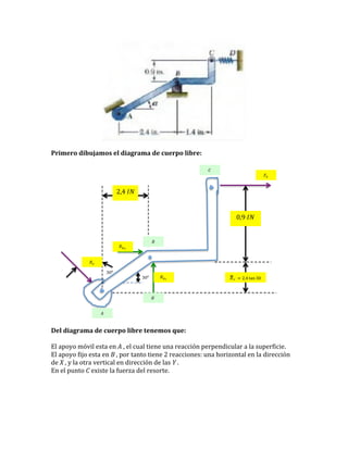
(a) Se dibuja el diagrama de cuerpo libre de la palanca BCD con apoyos en B y C.
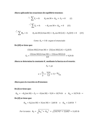
(b) Aplicando las ecuaciones de equilibrio, se determinan las reacciones en los apoyos B y C como RBy = 10.74 lb, RBx = 2.60 lb, y RC = 449 N.
(c) Usando la fuerza en el resorte Fs = 9.24 lb, se calcula la constante del resorte K = 7.7 lb/in.