Descargar para leer sin conexión
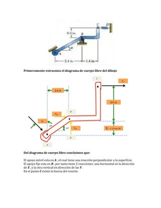
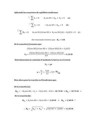

(1) Se extrae el diagrama de cuerpo libre de un dibujo que muestra un resorte y apoyos fijos y móviles; (2) Del diagrama se concluye que hay reacciones en los apoyos y una fuerza del resorte; (3) Aplicando ecuaciones de equilibrio se determinan las reacciones y la constante del resorte.


