Descargar como PDF, PPTX
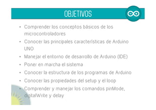
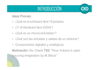
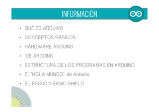
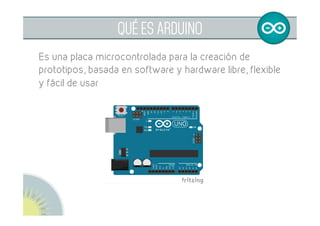
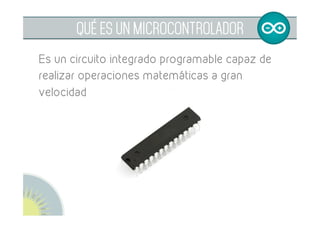
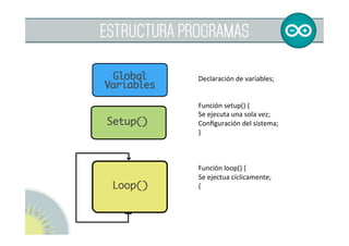
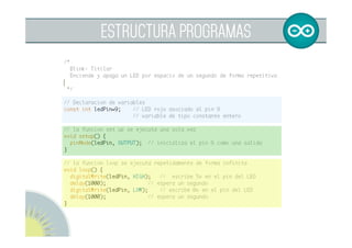
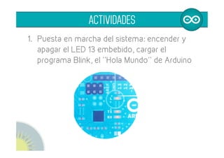
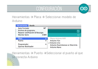
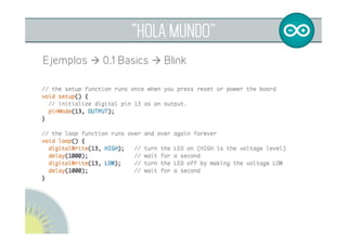
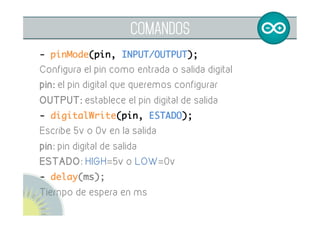
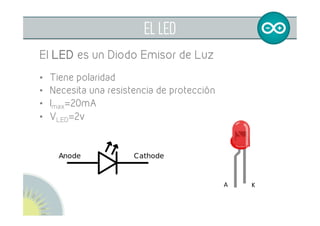
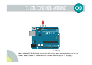
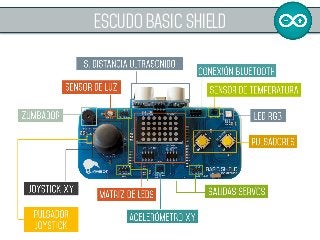
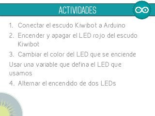

El documento ofrece una introducción a Arduino y su entorno de desarrollo, diseñando una serie de objetivos como el manejo de microcontroladores y la comprensión de diversos comandos. Se detalla la estructura de los programas en Arduino, así como ejemplos prácticos, incluyendo la activación de un LED y la conexión de un escudo. Finalmente, se enfatiza la importancia del software y hardware libre en la creación de prototipos.


![[Arqui1]practica2 200815555](https://cdn.slidesharecdn.com/ss_thumbnails/arqui1practica2200815555-140918220820-phpapp02-thumbnail.jpg?width=640&height=640&fit=bounds)


